Topics: Radio
The BITX40 is a QRP (low-power) transceiver kit for the 40 meter amateur radio band. Although it is low-power (nominal 7 watts), and restricted to a single band (7 MHz), the $60 USD price tag makes it very attractive to those like myself who like to build things and play around with radio on a budget.
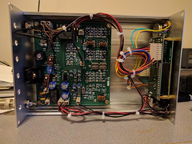
Usually when we think of an electronics kit, we imagine a big bag of components that need to be soldered together. In the case of the BITX40, all of the components have already been soldered to the PCB. You get the transceiver board, a digital control board, an LCD module, and all of the supporting hardware for the radio like a microphone, potentiometer, etc. The only things the end user needs to add are a speaker and enclosure. (And like any ham radio, a power supply and antenna.)
I started out trying to homebrew an enclosure out of galvanized sheet metal and aluminum angle bracket. It did not go well. We will no longer speak of it.
Turning to eBay, I found a variety of surprisingly affordable project boxes. This one here fits the BITX40 nicely with plenty of room to spare for mods and whatnot. It's built like a tank and is extremely high quality overall. You should be able to find it for around $20 shipped, just search for the dimensions "203x144x68mm".
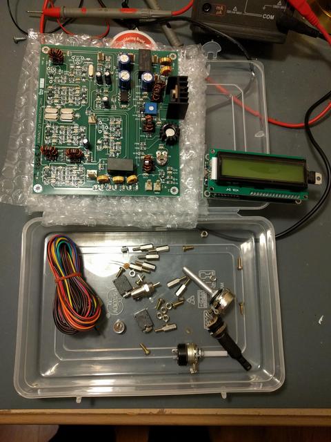
As she arrived. I ended up losing one of the standoffs somewhere. Also, it came with a tiny SMD capacitor in the box that I have not been able to divine the purpose of. Did not find it in the instructions, nor did any googling turn anything useful up. If anyone knows what it's for, let me know.
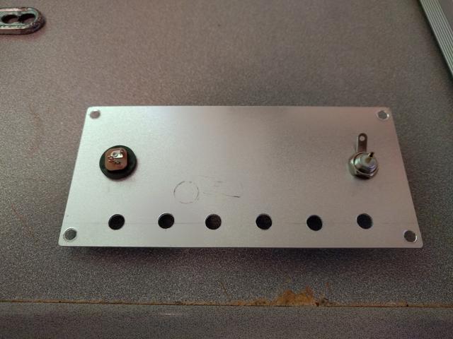
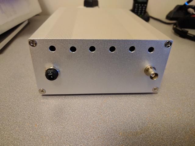
I started with the easy stuff. Power and antenna connectors mounted and vent holes drilled. In this picture they look very misaligned. in real life, it's hard to notice.
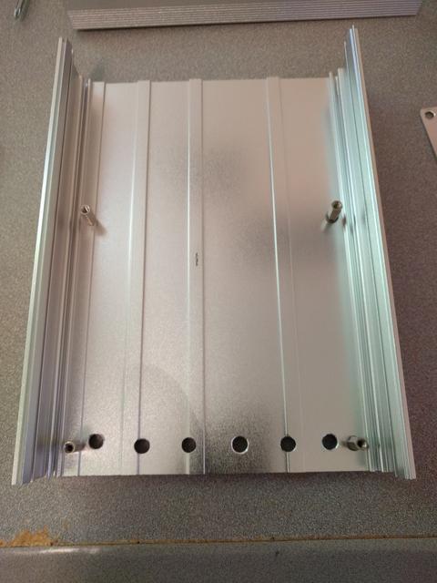
Drilled more vent holes in the bottom of the case and mounted the stand-offs. Again, not the best on alignment but these are on the bottom anyway, so whatev.
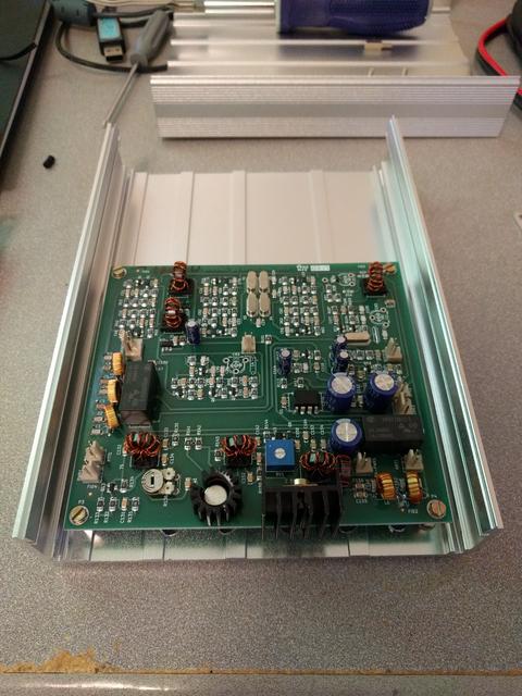
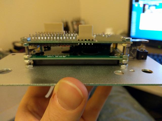
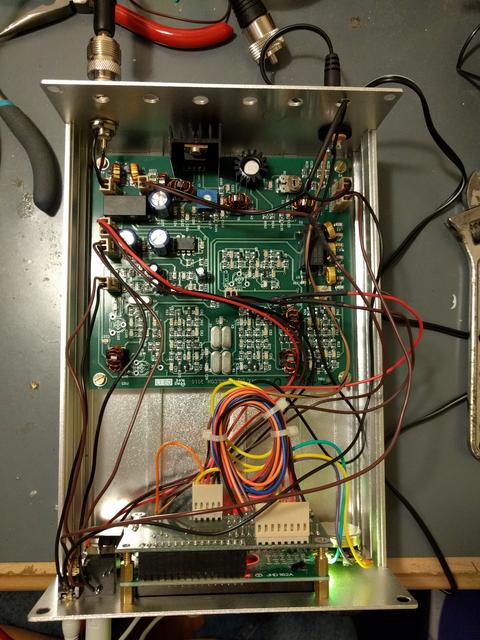
The BITX40 mainboard mounted up just fine. I wanted to have both the antenna connector and RF final transistor close to the back of the case. This achieves that. Some day, it will be fairly easy to add a bigger heat sink to the final transistor.
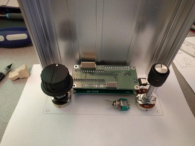
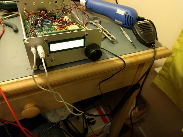
Now the hard part: Mocking up placement of front panel parts. In this photo, I'm just checking that everything fits comfortably on the 2D side of things. This is the first of three front-panel mock-ups that I did.
Trying to get the front panel layout right accounted for the vast majority of the time spent on this project. The project box came with two flat end panels. Messing one up wouldn't have been the end of the world, but it would have pissed me off greatly. So I tried very hard to get it right and checked everything multiple times every step of the way.
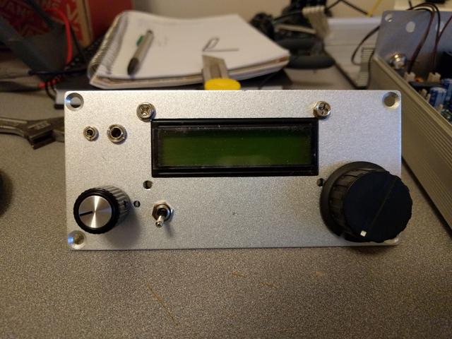
The volume pot that shipped with the BITX40 felt flimsy so I replaced it with one of my own. This knob doesn't have a switch built into it, so I had to add one off to the side. All the Radio Shacks around me are going out of business so I raided their goody bins one by one. Most of the "extra" parts you see here are from those sales, including the knobs.
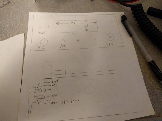
First rough draft of the front panel layout.
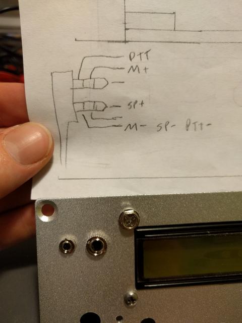
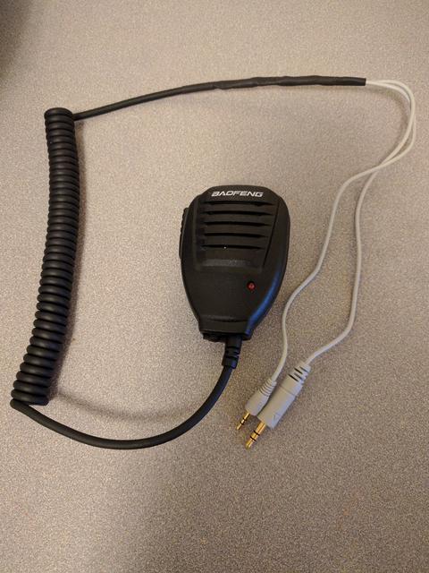
For the speaker and microphone, I decided to go with a Baofeng speaker mic. I mean, for $3.50 shipped, you'd be crazy not to, right? At the bottom is a pinout of the speaker mic, as deduced by multimeter. If you have a look at the first pic and then this pinout, you may be able to see where I was going to run into trouble later on.
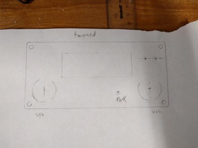
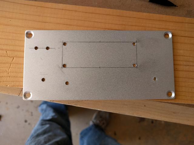
A more precise layout of the front controls (reversed).
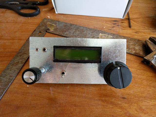
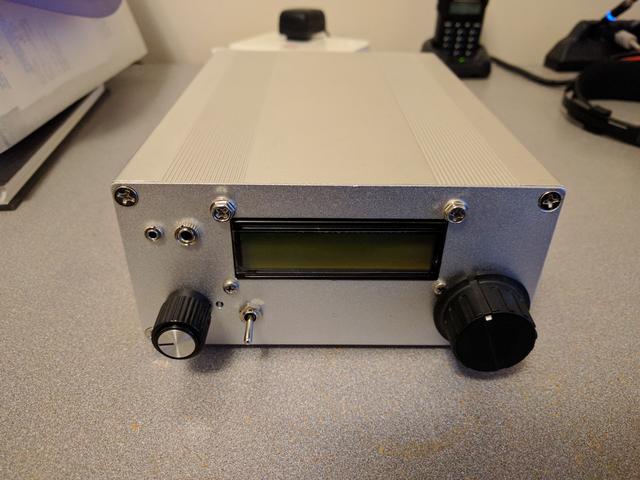
The final mockup using sheet metal. I ended up moving the power switch to the left about a centimeter so I have more room for switches and buttons and stuff later on.
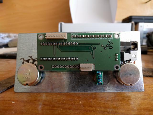
And a view of the rear of the mockup shows that everything is packed rather tightly together. This is why I was so careful about laying it out multiple times. I didn't want to be putting parts into the final panel only to discover that one thing physically interfered with something else.
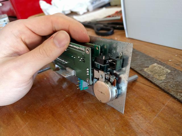
This is why I was so careful about laying it out multiple times. I didn't want to be putting parts into the final panel only to discover that one thing physically interfered with something else.
Thankfully, it was all good.
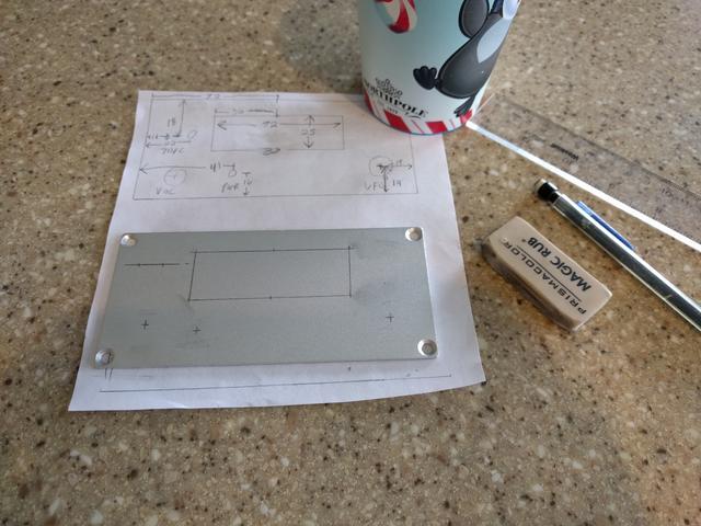
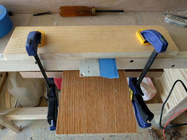
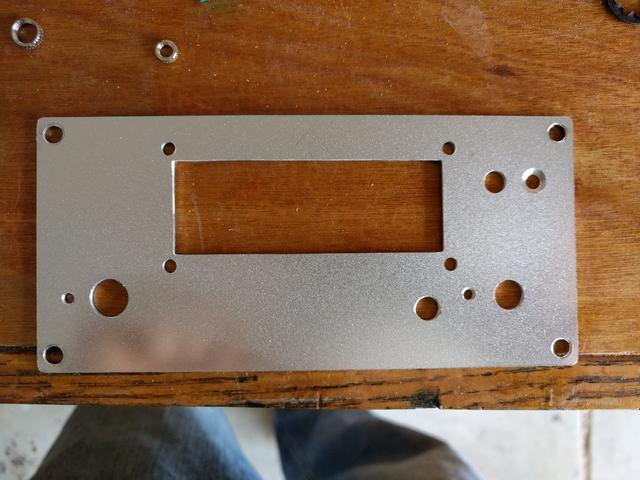
Starting to lay out the front panel.